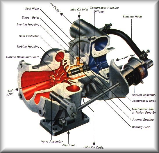
The turbocharger, or "turbo", is mounted directly to the exhaust manifold, where exhaust gasses pass over a turbine impeller that is attached to a short shaft. On the other side of this shaft is a compressor turbine, which pulls outside air in through the air filter and blows it into the intake manifold. So basically, the energy from the expelled exhaust gasses, which would normally be wasted on a N/A engine, is being used to pump air back into the engine. The shaft is supported by a bearing housing that is lubricated and cooled by an oil line from the engine. Since engine exhaust has such high temperatures, the exhaust side of the turbo can reach thousands of degrees F. This is why it is so critical that the engine oil be changed religously (every 3,000 miles), because old oil can burn and leave deposits in oil lines and housings, called "coke". Coking can be virtually eliminated by using a synthetic oil and changing it frequently (every 6,000 miles). After 1985, the turbos featured an additional passage for a coolant line, to keep the bearing housing cool. This did little to keep temperatures down while running, but it had a huge effect after the engine was shut off. Without the coolant passage, the oil would drain when the engine was shut off and the turbo bearing housing would reach incredibly high temperatures from the heat transferring out of the exhaust manifold. This took its toll on the life of the bearings. The presence of the water keeps the housing cool. Here is a picture showing a cutaway of a turbochager (this one does not have a coolant passage and features a mechanically-controlled wastegate):
When the engine has been idling or at low speed for a while, the turbo
is not spinning or is spinning very slowly because there is very little
exhaust leaving the engine. When the throttle is opened, the engine
produces more exhaust, which spins the turbo faster. A faster spinning
turbo means more air and fuel is being blown into the engine, therefore
even more exhaust is being produced, which makes the turbo spin even faster
and so on. This cycle is known as turbo "spool-up", which feels like
a sudden surge in engine power and appears on your boost guage as a sudden
increase in pressure. The time before the surge, when the turbo is
spooling up but the engine doesn't have much power yet, is called turbo
lag. A large turbocharger can produce more air flow and pressure,
but will have more lag because of its increased size. A small turbocharger
will have a smaller amount of lag, but will not be able to move as much
air. This is explained in more detail is the sections below.
The exhaust turbine's job is to convert the energy in the moving and expanding exhaust gasses into rotating kinetic energy of the shaft and turbines. The compressor turbine's job is to convert that rotating energy into the movement of the air that enters the engine. This air is compressed and (unfortunately) heated. The turbines in a turbocharger are measured by the sizes of each stage of the turbine. A turbine has two stages: the inducer stage and the exducer stage. The size and shape of each stage determines the shape of the turbine's fins and ultimately the characteristics of that turbine.
For the compressor turbine (or "compressor wheel"), the inducer part of of turbine is at the end of the shaft and can be seen by looking into the intake of the turbo compressor housing (looks like a fan). The blades that you see there extend into a larger diameter at the other end of the turbine. This is the exducer stage. The inducer on the compressor turbine is responsible for generating the vacuum at the compressor housing inlet that pulls air into the compressor. The air then "rides" the fins towards the exducer stage, which is a larger diameter, and gets sling-shot towards the ouside of the compressor housing. The housing collects this moving air an expells it through the housing's outlet. The way that the air leaves the fins causes it to swirl as it leaves the housing. Since the intake manifolds on the early Turbo I engines were so close to the turbo, an anti-swirl fin had to be installed in the turbo outlet duct to stop this air motion from effecting the flow characteristics of the intake manifold.
The exhaust turbine also has an inducer and exducer, but because the
exhaust turbine has the opposite function of the compressor turbine, the
two are switched. The exhaust gasses are directed towards the outside
of turbine through a nozzle. This is the inducer stage because it
is the part of the turbine that collects the gasses. As the energy
from the gasses is transferred into the turbine, the gasses slow down and
exit the turbine through the exducer stage.
On the compressor side, the housing also features a scroll design, but
it has the opposite function. The air leaving the compressor turbine
has a lot of speed, but not much pressure. The scroll on the compressor
housing starts small and gets larger as it approaches the compressor outlet.
This collects the air and builds up air pressure. So, the compressor
housing is designed to convert the speed-energy of the air coming off of
the compressor turbine into pressure-energy, which is much more useful
to an engine.
So in conclusion, a turbocharger's design becomes a balancing act between
these three factors (whew!). The rest of this page won't give you
a headache like these sections did. :)
One step up from this is the Turbo II, which features an air-to-air intercooler installed next to the radiator. The intercooler's purpose is to cool down the extremely hot air coming out of the turbo. This serves two purposes. One is to decrease the inital temperature of the air/fuel mixture entering the engine, which serves to reduce detonation and permit higher boost levels. The second reason is that cooler air is denser, therefore more air can fit into the combustion chamber. So you can see that denser air at higher pressure allows the engine to produce more power. This is illustrated by the improved performance of 175 HP at 5200 rpm and 175 ft-lbs from 2200-4800 rpm.
 In
1991, the Turbo III engine was breifly produced by Chrysler. This
engine was mainly identical to the Turbo II setup except that it featured
a new head designed by Lotus, which was a DOHC (dual overhead cam), 16
valve engine. It also had a different turbocharger. The extra
air flow gave this engine 224 hp at 6000 rpm and 217 ft-lbs at 2800 rpm,
but the head is known to have a high failure rate.
In
1991, the Turbo III engine was breifly produced by Chrysler. This
engine was mainly identical to the Turbo II setup except that it featured
a new head designed by Lotus, which was a DOHC (dual overhead cam), 16
valve engine. It also had a different turbocharger. The extra
air flow gave this engine 224 hp at 6000 rpm and 217 ft-lbs at 2800 rpm,
but the head is known to have a high failure rate.
The most elaborate turbo setup was the Turbo IV VNT (variable nozzle
turbo). It was a breakthrough in turbo design because it featured
a type of turbo that reduced turbo lag to almost nothing. It has
a larger exhaust housing, so it can produce higher boost with ower back
pressure, but it has moveable fins located around the exhaust turbine.
When the vents are mostly closed, the exhaust gasses are sped up (since
they are passing through a smaller oriface) and the turbine is spun faster.
When they are opened, the gasses slow down but there is a larger amount
of gasses to spin the turbine and give it more pumping power. When
the throttle is opened at idle, the computer-controlled vents momentarily
pinch off the exhaust to quickly spin the turbo, but open them right away
to keep from bogging the engine with the restricted exhaust. The
quick spin-up gives the engine more power right away and the vents will
close and open for the maximum amount of power build up. With this
setup, no wastegate is necessary because the wide-open vent can slow the
turbo down, even when the engine is at maximum output. Since this
engine was intercooled, but did not feature the Lotus head, power output
is still 175 HP but the torque is up to 200 ft-lbs at 3700 rpm.
<turbo setup diagram>
The reason for the change in the Turbo I in 1988 was probably more a matter of convenience than of performance, proven by the fact that there was no performance gain by the change. This way, Chrysler didn't have to have two completely different intake setups for its Turbo I and Turbo II engines. In fact, the blow-through design is actually more complicated than the pull-through, because of what happens when the throttle is closed. One problem with the pull-through intake is that if a hose comes off of the turbo, it would be like having a wide open throttle to the engine because the throttle body is being bypassed. I have never heard of this happening to anyone, but it is possible.
On a pull-through intake, when the turbo is boosting and the throttle is suddnely shut (while shifting, for instance), a huge vacuum is generated between the engine and the throttle body, and the turbo is spinning in a low-pressure environment. This is good because then there is less air friction to slow the turbine, and so there will be less lag when the throttle is opened again. However, it takes a moment for the compressor turbine to get the air flowing fast again, since the air was at a dead stop. On the blow-through intake, when the throttle is closed, a huge pressure spike is produced between the turbo and the throttle body, because the turbo is blowing against a closed throttle plate. This slows the turbo down very quickly and there is a lot of lag when the throttle is opened again. The pressure spike is also hard on the turbo and intake hoses. To remedy this, the production blow-through setup features a blow-off valve (BOV) on the output hose of the turbo. This is a large, vacuum actuated valve that opens when there is vacuum in the intake manifold (closed-throttle). This valve vents off the pressure spike, avoiding the quick spool-down of the turbo and potentially damaging pressure spikes. Although the turbo still slows down more than the pull-through setup does during the time that the throttle is shut, pressure is brought back up just as quickly because the air is still moving. When the throttle plate is opened again, the BOV immediately shuts and the air flow is directed back into the engine. Also, the 1988 and later Turbo I engines had a smaller turbo, which further reduced the lag. So all in all, the two setups are about even in performance. For more details on BOVs, see the Blow-Off Valves page.
If you have a Turbo II engine (including the Shelby engines), your engine
will not have a BOV installed. To see a significant decrease in inter-shift
lag, install a BOV on one of the pressure hoses. See the Blow-Off
Valves page for instruction on how to do this.
| Return to the Mini-Mopar Turbo Performance page |
This page is maintained by Russell W. Knize and was last updated 01/19/99. Comments? Questions? Email minimopar@myrealbox.com.
Copyright © 1996-2003 Russ W. Knize