Electrical Issues: Main Power Feeds
Symptoms
There is a problem with a power feed in the electrical system. There are several levels of power feeds and this page will help you track down the problem.
Diagnosis
To diagnose a power feed problem, use the list below to narrow down the source of the problem:
- No power at all: no power to accessories (headlights, radio, etc) and nothing happens when the ignition is turned on.
- No ignition feed: the instrument panel (lights, chimes, etc) does not come on and the engine does not crank, but accessories (headlights, radio, etc) have power.
- Starter problem: the engine does not crank, but the accessories (headlights, radio, etc) and instrument panel (lights, chimes, etc) have power.
- No engine feed: the engine cranks, but there is no spark, fuel, etc. Accessories and instrument panel work.
- No radiator fan feed: the engine runs, but radiator fan and air conditioning do not work
- No rear window defroster feed: everything works except the rear window defroster and/or under hood light
If you do not see your exact symptoms here, try the closest one. In order to do ANY of these tests, you really need to have at least a DC voltmeter. A multimeter that can measure DC voltage, current, and resistance is much more useful. If you don't have a multimeter and plan on doing anything automotive, go and get one right now. You can get a cheap analog multimeter (or "multitester") for $10, but I recommend getting a digital one because they are much easier to read quickly and many are auto-ranging (you don't have to select the range and worry about blowing it up). You can get those for around $10 to $20. If you are serious, you can spend $40 - $100 on a good, digital multimeter than can measure high currents with fuse protection, etc.
No Power At All
Use this section if your vehicle has no power at all. This means that the always-on accessories, such as headlights and the interior dome light, do not work. When the key is turned to the "accessories" position, no other accessories (radio, fan, etc) have power. When the key is turned to the "on" position, the instrument panel does not come on (power loss/check engine and oil lamps). When the key is turned to the "start" position, nothing happens.
The most common source of this problem is battery-related. Follow this procedure to track down the problem:
- Turn the ignition to the "off" position. Turn the headlight switch on. If the headlights turn on, go to the No Ignition Feed section. Open the hood to the engine compartment.
- Check the battery
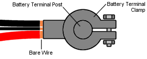
- Measure the battery voltage at the battery terminal posts, NOT the terminal clamps (see the diagram below). Be sure to scratch the surface of the post with the meter's probe to ensure a good connection.
- If you see zero or just a few volts, your battery is dead. Either use jumper cables to try and start your car, put a car battery charger on it, or replace the battery. If your battery keeps dying, see the Diagnosing Your Charging System page.
- If you see around 10V-12V across the battery, then the battery is good.
- Check the terminal connections
- Measure the voltage at the battery terminal clamps, NOT the posts (see the diagram below). Be sure to scratch the surface of the terminal clamp with the meter's probe to ensure a good connection.
- If you see zero of just a few volts, then your battery terminals are corroded.
- Measure the voltage between the terminal post and the terminal clamp for each side of the battery. You should measure some voltage across at least one of the terminals; this is the corroded terminal. If not, then you did not get a good connection during one of these tests. Disconnect both battery terminals from the battery and clean the inside of the terminal clamp and the outside of the terminal post with a wire brush or battery terminal cleaner. If the terminal clamps seem to be falling apart, they should be replaced. It is a good idea to coat the terminals with grease or battery terminal spray and cover them with terminal covers to avoid further corrosion. You can also get felt washers that absorb the acidic gasses that come out around the terminal posts.
- Repeat the test to see if you found the problem.
- If you see around 10V-12V across the terminals, then your terminal clamps are OK.

- Check the ground connections.
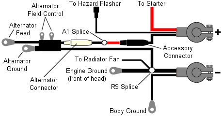
- The diagram below gives a typical wiring setup for the battery connections (based off of 1987 configuration). Typically, the battery ground is connected to the rest of the vehicle in three or more places. These include the body, the engine, and the alternator. To test these connections, place your meter's positive probe to the positive battery terminal.
- Now place the negative probe somewhere on the body or frame where you can get in contact with metal. The bolts on the left strut tower is a good choice. You should measure the same voltage you measured across the battery (10V-12V). If you don't see a voltage here, make sure you are getting a good connection with the meter. If so, check the body ground, which is usually a black, 10 gauge wire that is bolted to the body or frame behind the battery.
- If the body ground is OK, then connect the negative probe from your meter to the engine block or head. Make sure the probe is reaching bare metal. Again, you should measure 10V-12V here. If not, check the engine ground, which is a black 6 gauge wire that is connected to a boss on the corner of the head near the spark plug for cylinder #4.
- If you can't measure a ground in either place, connect the negative probe right to one of the two ground lugs. If there is no reading, then the negative battery terminal may be bad. This is usually evident by severe corrosion on the wires as they enter the back of the terminal clamp. The stock terminal clamps are molded onto the wires, so you will have to cut off the wires as close to the clamp as possible and strip the insulation off to install the new ones.

- Check the positive feeds.
- Connect the negative probe from the meter to the battery's negative terminal.
- Disconnect the accessory connector. This is a black, tube-shaped connector a few inches from the positive battery terminal. Connect the meter's positive probe to the contact in the female side of the connector. You should measure 10V-12V here. If you don't see that voltage here, then you probably have a bad battery terminal. Otherwise, your problem may be the power distribution at the A1 splice.
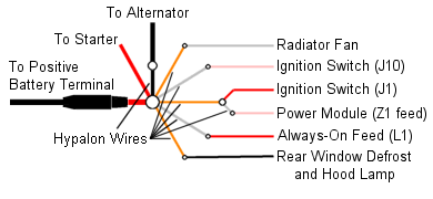
- The A1 splice is the main power distribution for the whole electrical system. If your vehicle is an 1989 or earlier model, then you probably have hypalon wire fusible links. Otherwise you should have a power distribution box (contains removable fusible links or maxi-fuses, and relays) under the hood, near the battery. The diagram below shows a typical A1 distribution (using hypalon wires, based off of 1987 configuration).

- See the Electrical Issues: Fusible Links for information on how to diagnose and repair fusible links.
- If all fusible links seem to be intact, then there is probably a wiring problem between the A1 distribution and the ignition switch and/or fuse box. You will need to consult the wiring diagrams for your vehicle to aid in tracking down the problem.
If you made any of the above repairs, but are still having electrical problems, go back to the Diagnosis section to find the next problem.
No Ignition Feed
Use this section if the instrument panel (lights, chimes, etc) does not come on when the ignition is turned to the "on" position. The engine does not crank when the key is turned to the "start" position. However, the accessories (headlights, radio, etc) have power.
This condition is almost always a blown fusible link. The main power to most of the engine's systems comes from the J2 splice. The J2 splice is powered through the ignition switch from the J1 feed. As you can see by the diagram below, the J1 feed comes right from the battery, through a fusible link. The diagram shows hypalon wire fusible links, but your vehicle may have a power distribution and relay box near the battery. Inside are the removable fusible links and a diagram describing them.

The hypalon wire fusible links look just like regular wires. The easiest way to test them is to tug on them. A blown link will stretch like a rubber band. Other fusible links usually have a window on them, showing the link itself. If it looks blown, replace it. Hypalon links have to be spliced back together. If there is enough wire left to splice, a butt crimp-connector works well. Otherwise, you will have to add some wire and somehow splice it back in. If all fusible links seem to be intact, then there is probably a wiring problem between the A1 distribution and the ignition switch or the switch itself may be bad. You will need to consult the wiring diagrams for your vehicle to aid in tracking down the problem.
Starter Problems
Use this section if the engine does not crank when the ignition key is turned to the "start" position. However, the accessories (headlights, radio, etc) and instrument panel (lights, chimes, etc) have power. This condition has two possibilities that are the most common. You can narrow it down somewhat this way:
- Make sure your battery is healthy.
- Turn the key to the "start" position.
- If you hear a fairly loud click or clunk coming from under the hood, then your starter relay and solenoid are probably working. Check the main positive lead to the starter and make sure the connections on the back of the starter are secure. If the starter is getting power and the solenoid is working, then the starter is probably bad, or your battery is very weak.
The starter relay is usually located on the left strut tower, or inside the power distribution and relay box. It is usually wired as shown in the diagram below, which is based off of the 1987 wiring. If you have relay box, use you wiring diagrams to determine which pins do what. Use the following procedure to located the problem:

- Disconnect the relay from the harness or relay box.
- Connect the meter's negative probe to ground or the negative battery terminal. Measure the voltage at the A1 feed contact with the meter's positive probe. It should be 12V at all times. Some systems have a fusible link on this line, while others are directly connected to the battery.
- Now connect the positive probe to the ignition switch wire. Have someone turn the ignition key to the "start" position. You should measure 12V here. If not, there may be a wiring problem, or a problem with the ignition feed.
- Connect the positive probe from your meter to the positive battery terminal. Connect the negative probe to the neutral safety contact. You should measure around 12V. If you have a manual transmission, this wire should always be grounded at the top center transmission bell housing bolt. If you have an automatic transmission, this wire should be grounded by the neutral safety switch on the transmission. Assuming your transmission is in "Park" or "Neutral", if you do not measure a voltage here, then the switch is probably bad.
- If everything checks out, reconnect the relay and have someone turn the key to start. You should be able to hear or feel the relay click on. If not, the relay may be bad.
- If the relay does click on, then you need to check the relay output. The wire to the starter solenoid should go through a connector near the battery. Look for the pin with the same wire color as you saw on the solenoid (brown in this example). You should be able to shove your meter's prob into the back of the connector to get a reading. When the ignition key is turned to the "start" position, 12V should appear here.
- If no voltage is present at the connector, then either the relay is bad or there is a wiring problem.
- If 12V is present, then the starter solenoid may be bad, or the wiring to the solenoid is faulty.
No Engine Feed
Use this section if the engine cranks when the ignition key is turned to the "start" position, but there is no spark, fuel, etc. Also, the accessories and instrument panel work. This problem can have several causes and may take some time to track down.
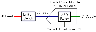
Basically, most of the engine's components that require 12V get it through the J2 or Z1 feeds. The Z1 feed is basically the J2 feed switched on and off by the ASD Relay. On 1987 and earlier models, the ASD relay was located inside the power module. For later models, it was a black plastic relay located externally, near the other relays. The ASD Relay is controlled by the computer and is turned on when the computer detects a signal from the ignition reference sensor.
The J2 feed supplies power to all of the solenoids, some relays, the alternator field, oxygen sensor, diagnostic connector, etc. It almost always is a dark blue 14 gauge wire. If you do not see a dark blue wire, look for a common wire color on all of the solenoids. This should be your J2.
- Turn the ignition key to the "on" position.
- With the negative probe of your meter grounded to the chassis or negative battery terminal, use the positive probe to check for the J2 voltage at a solenoid. Look for the common wire color (usually dark blue). Now check for it at all solenoids, any relay that has that wire, the alternator field terminal (usually the top one, see the battery connections diagram in the No Power At All section), and at the power module, SMEC, or SBEC (see the Understanding The Chrysler ECU page if you don't know what these are).
- If you find the voltage at every place where you saw that wire, then your J2 feed is probably good. Make sure you checked for it at the power module or ASD relay and SMEC/SBEC.
- If you couldn't measure it anywhere, then your J2 feed from the ignition switch is bad. Check the wiring and replace the switch if necessary.
- If you only measured it in some spots but not others (particularly at the power module, SMEC or SBEC), then you have a bad splice. The J2 splice is actually a series of two or more splices. Usually, two of them are in the harnesses near the battery and fumes from the battery causes them to corrode and break. Consult your wiring diagrams for exact splice locations and repair any bad ones.

Now you need to check the Z1 feed. The Z1 feed supplies power to the ignition coil, fuel pump and fuel injectors. If you have a 1987 or earlier vehicle, the Z1 feed comes right out of the power module (the ASD relay is inside). On later models, the Z1 feed comes from the ASD Relay.
- Turn the ignition key to the "on" position.
- With the negative probe of your meter grounded to the chassis or negative battery terminal, connect the positive probe to Z1 supply to the ignition coil (may be dark green and may be with a black stripe...consult your wiring diagrams).
- Have someone crank the engine while you watch the meter. As the engine is cranked, 12V should appear on the coil.
- Repeat the test for the fuel injectors and the fuel pump. Stick the positive probe into the fuel injector connector by the rail to measure there. For the fuel pump, measure the voltage at the fuse panel by pulling the fuse and testing on each of the two contacts.
- If you find the voltage at every place where you saw that wire, then your Z1 feed is probably good.
- If you only measured it in some spots but not others, then you probably have a bad splice. Consult your wiring diagrams for exact Z1 splice location on your vehicle.
- If you couldn't measure it anywhere, then your Z1 feed from the ASD relay is the problem.
- Connect the positive probe from your meter to the positive battery terminal and use the negative probe to test the ASD control line. If you have a 1987 or earlier vehicle, this wire leads to the power module (pin 5 of the 12-way connector, dark blue with a yellow stripe). Try to push the probe through the back of the connector into the contact. If you have a later model, you can disconnect the ASD relay and connect the probe there.
- Have someone crank the engine. While the engine is cranked, 12V should appear at the relay control line.
- If a voltage appeared, then your relay is probably bad, but you may want to check the connections. Verify that the power module or relay is getting the J2 feed and that the Z1 output makes a good connection. If you have a power module, the entire module has to be replaced. If you are good with electronics, the unit can be disassembled and the relay replaced (with some difficulty). Otherwise, just replace the relay.
- If no voltage appeared, then it is likely that the computer is not seeing a signal from the ignition reference sensor. You may want to consider replacing it. Be sure that you have good connections at the sensor. The contacts in those two round connectors are prone to getting loose. Be sure that the cables to the sensor are properly secured so that they don't swing around and damage the wires inside.
No Radiator Fan Feed
Incomplete.
No Rear Window Defroster Feed
Incomplete.
Updated 01/04/2005.
Copyright © 1996-2005 Russ W. Knize.


